
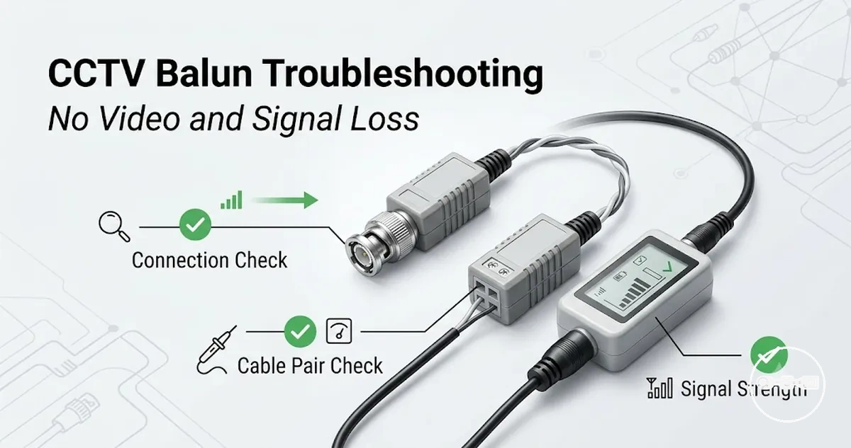
CCTV Video Balun Troubleshooting for No Video and Signal Loss
CCTV Video Balun Troubleshooting for No Video and Signal Loss defines the diagnostic scope for identifying why video transmission fails or degrades in a CCTV signal chain. It focuses on how CCTV video balun systems behave when video disappears, becomes unstable, or shows distortion across UTP cable runs. The troubleshooting context treats each failure as a signal-chain breakdown rather than a single isolated defect. This includes the interaction between cable integrity, connector quality, impedance matching, and transmission limits across the system. Symptoms such as no video, flickering, or noise are interpreted as diagnostic signals that indicate where the breakdown may be occurring. The purpose of this scope is to support structured fault recognition before any corrective action is considered.
Signal loss in CCTV video balun systems may occur when one or more parts of the transmission path are no longer maintaining stable electrical continuity or signal balance. Common contributing factors can include degraded UTP cabling, loose or oxidized connectors, impedance mismatch between connected components, or compatibility issues between different balun types. In many cases, distance-related attenuation can also weaken the signal to a point where it becomes unstable or disappears entirely. These conditions do not indicate a single fixed failure point but rather a set of possible system-level causes that must be evaluated through observation of symptoms.
No video and image distortion represent different failure behaviors within the same signal chain. No video typically indicates a more complete interruption of signal transmission, where the output cannot be reconstructed at the receiver. Image distortion, on the other hand, often appears as partial signal degradation such as noise, rolling lines, or unstable brightness, where some level of transmission is still occurring. Both scenarios can share underlying causes such as connector instability, cable degradation, or compatibility mismatch, but they present different diagnostic patterns that help narrow the fault location within the system.
How CCTV Video Balun Failures Affect Video Signal Transmission
CCTV video balun failures affect video signal transmission by disrupting how video signals are carried over UTP cabling between camera and recorder systems, often through changes in signal balance, impedance behavior, or attenuation levels. This mechanism can be understood through the CCTV video baluns hub context, where the balun condition influences how effectively analog or HD signals remain stable across the transmission path. When a CCTV video balun becomes faulty, mismatched, or degraded, the signal flow may lose consistency depending on cable quality, distance, and termination accuracy. The effect is not always a complete breakdown, but a shift in signal integrity that reduces clarity or stability under specific conditions.
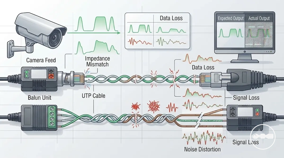
The transmission impact is typically linked to how electrical balance is maintained across twisted pair cabling. If impedance mismatch occurs between connected components, the signal can reflect or weaken as it travels, increasing the likelihood of degradation over longer cable runs. In other cases, attenuation may gradually reduce signal strength until the receiver can no longer reconstruct a stable video feed. These effects usually depend on the combined condition of the balun, cabling environment, and termination quality rather than a single isolated fault.
Different failure conditions can influence signal behavior in distinct ways. A partially degraded balun may still pass video but with reduced stability, while a more severe mismatch or connection issue may interrupt transmission more significantly. The outcome varies based on how multiple factors interact within the signal chain, making CCTV video balun failures a system-level issue rather than a single-point defect.
Common CCTV Video Balun Problems: No Video, Signal Loss and Poor Image Quality
Common CCTV video balun problems appear as three primary symptom groups: no video at the display, intermittent signal loss, and degraded image quality such as noise, flickering, or rolling distortion. These symptoms are used as direct recognition signals to indicate that the CCTV video balun or its transmission path is not maintaining stable video delivery across the UTP link. Each symptom reflects a different level of signal interruption, ranging from complete absence of output to partial degradation of image clarity under varying cable conditions.
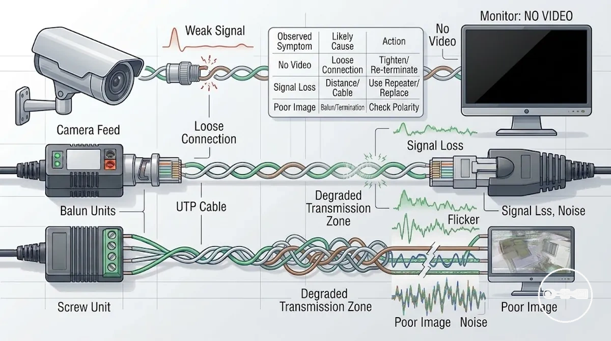
No video is typically associated with a full interruption in the signal path, which may occur when continuity is broken or when a connection becomes completely unstable. Intermittent signal loss often reflects an unstable transmission path where the signal appears and disappears, sometimes linked to inconsistent contact or fluctuating line conditions. Poor image quality is generally observed as noise, rolling images, or visual distortion, indicating that the signal is still present but has degraded during transmission.
These symptom patterns can often be grouped into underlying system conditions such as open circuit states, loose or unreliable connections, or instability across the transmission path. The relationship between symptom and condition is not fixed, but the pattern helps narrow down where the CCTV video balun system may be failing within the overall signal chain.
Interference Patterns in CCTV Video Balun Systems: Noise, Horizontal Lines and Ground Loops
Interference patterns in CCTV video balun systems appear as visible image distortions such as noise, horizontal lines, or rolling artifacts caused by external electrical influence or grounding imbalance affecting video stability during transmission. These patterns indicate that the CCTV video balun signal is still present but being disturbed by environmental or electrical conditions rather than being fully interrupted.
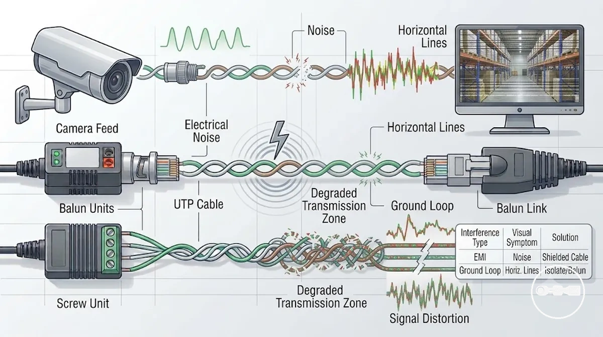
Noise interference typically shows up as static-like visual disruption that reduces image clarity without fully removing the video feed. Horizontal lines often appear as moving or fixed bands across the screen, reflecting instability introduced into the transmission path. Ground loop effects may present as rolling distortion or brightness shifts, often linked to differences in electrical potential within the system environment.
Unlike complete signal loss scenarios, interference-driven degradation maintains partial video output while affecting quality and stability. This distinction helps identify environmental or electrical influence as the primary factor, rather than a total break in the CCTV video balun transmission path.
CCTV Video Balun Cable Distance Limits and Transmission Degradation
CCTV Video Balun Cable Distance Limits and Transmission Degradation depends on cable quality, signal type, and environmental conditions, where increasing transmission length typically affects signal stability through gradual attenuation and reduced overall video integrity. As the cable run extends, the CCTV video balun system may shift from stable transmission to progressive degradation depending on how strongly the signal can maintain balance across the UTP medium.
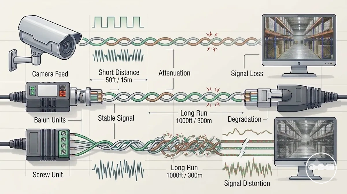
As distance increases, common effects may include weakening signal strength, increased susceptibility to noise, and reduced clarity in the received video image. These conditions are typically gradual rather than abrupt, meaning the system may still function while exhibiting progressive quality loss influenced by cable condition, termination quality, and external electrical environment.
Overall compatibility in CCTV video balun setups is shaped by how well the transmission path maintains signal integrity over distance, with degradation patterns serving as indicators that the system is approaching its effective operational boundary under given installation conditions.
Connector, Termination and Wiring Faults Causing CCTV Video Signal Failure
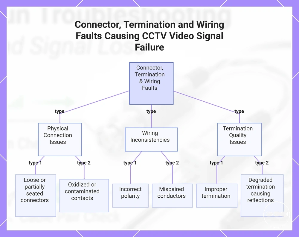
Connector, termination, and wiring faults causing CCTV video signal failure typically appear when unstable physical connections, misaligned terminations, or inconsistent wiring polarity affect the signal path, leading to symptoms such as intermittent video, distortion, or complete loss of image. When these symptoms occur, the likely cause is often located at the connection or termination points rather than within the transmission medium itself.
Loose fittings or partially seated connectors can introduce unstable contact conditions that interrupt continuous signal flow, while oxidized or contaminated contacts may gradually reduce signal quality until the video becomes noisy or disappears. Wiring inconsistencies, including incorrect polarity or mispaired conductors, can further distort the balanced transmission behavior expected in CCTV video balun systems.
Termination quality also plays a key role in maintaining stable signal integrity, where improper or degraded termination can create reflection-like effects that appear as flickering or rolling distortion. These issues are often dependent on installation conditions and may vary across different points in the same system.
In many cases, diagnosing these faults involves tracing how connection quality changes along the signal chain, including at endpoints and junctions. More context on structured connection methods can be found in CCTV video balun connectors and termination options, which relates to how termination consistency influences overall signal stability.
This chart shows the three main types of connection faults that disrupt CCTV video signals, along with specific examples of each fault type.
Active vs Passive CCTV Video Balun Compatibility Issues in Fault Scenarios
Active vs passive CCTV video balun compatibility depends on signal handling method, impedance alignment, and system-level matching, where mismatches between amplification-based active units and non-amplified passive units may lead to unstable or degraded transmission in fault scenarios.
When incompatibility occurs, symptoms may include weak output, flickering video, or an unstable feed, often linked to differences in signal processing levels or impedance behavior between active signal conditioning and passive balancing in the transmission chain.
These mismatch conditions are sometimes better understood through related cases of active and passive signal issues, where interaction between different balun types highlights how compatibility boundaries can affect video stability under fault conditions.
This chart shows the main causes and observable symptoms of compatibility issues between active and passive CCTV video baluns in fault scenarios.

Structured Diagnosis Process for CCTV Video Balun Signal Problems
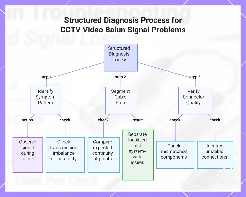
Structured diagnosis process for CCTV video balun signal problems refers to an organized troubleshooting approach that isolates faults by analyzing signal behavior step by step instead of relying on random or isolated checks. It focuses on how the CCTV video balun system responds under different conditions to narrow down the source of instability or failure.
The process typically begins with identifying the overall symptom pattern and observing how the video signal behaves during failure states. These behavior changes help indicate whether the issue is related to transmission imbalance, connection instability, or compatibility-related disruption within the system.
Next, the cable path is logically segmented to determine where signal degradation or interruption may be occurring. This isolation approach helps separate localized issues from system-wide inconsistencies by comparing expected signal continuity with actual output behavior at different points.
The final step involves verifying connector quality and compatibility conditions across the transmission chain. This includes checking whether mismatched components or unstable connections are contributing to irregular signal performance, allowing clearer identification of the underlying fault source.
This chart shows the structured diagnosis process for CCTV video balun signal problems, organized into three main steps: symptom identification, cable path segmentation, and connector verification.
Step-by-Step Isolation Checks for CCTV Video Loss and Signal Degradation
Isolation checks for CCTV video loss and signal degradation follow a structured sequence that separates cable, connector, and balun-related issues by observing how the signal changes after each controlled test variation.
The first step involves swap testing, where CCTV video balun units are exchanged between a known working channel and the affected channel to determine whether the fault follows the device or remains within the same cable path. This helps indicate whether the issue is device-related or transmission-related.
The next step focuses on continuity checks along the cable path, verifying whether the signal line maintains stable electrical continuity without breaks or irregular resistance behavior. In cases where instability is linked to installation issues such as wiring mistakes, this stage helps narrow down structural inconsistencies in the line.
The final step uses substitution with known-good components, where cables, connectors, or baluns are temporarily replaced with verified working parts to confirm whether signal degradation persists. This comparison-based isolation helps validate whether the issue originates from a specific component or from the overall system configuration.
Testing CCTV Video Baluns to Confirm Fault Before Replacement
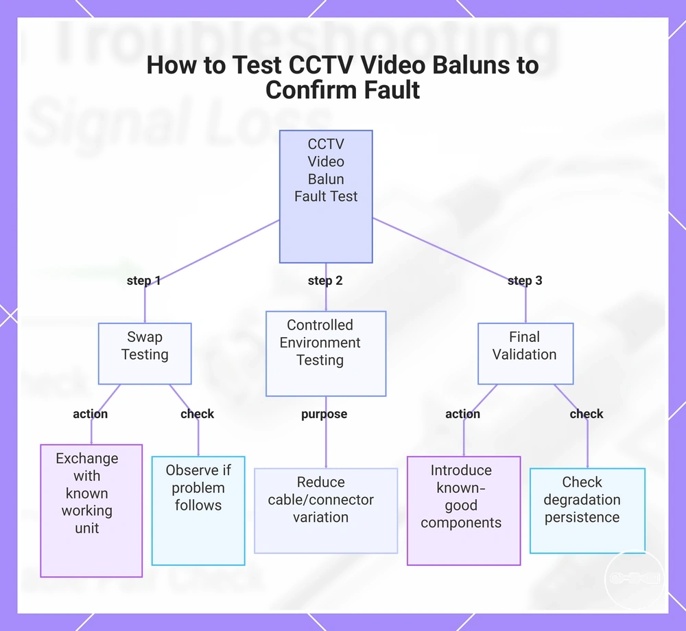
Testing CCTV video baluns to confirm fault before replacement depends on validation-based checks that determine whether signal instability is caused by the balun unit or by other parts of the transmission path.
The process typically uses swap testing and comparison-based observation, where a suspected CCTV video balun is exchanged with a known working unit to see whether the problem follows the component or remains within the same cable channel. In structured workflows, technicians may also test CCTV video baluns under controlled conditions to reduce misinterpretation caused by cable or connector variation.
A final validation stage relies on known-good system confirmation, where stable components are introduced into the same setup to check whether signal degradation persists. This helps ensure the CCTV video balun is only considered faulty when repeated and consistent evidence supports that conclusion.
This chart outlines the step-by-step validation process for confirming whether a CCTV video balun is faulty, using swap testing, controlled conditions, and final known-good confirmation.
When CCTV Video Balun Replacement Becomes Necessary After Troubleshooting
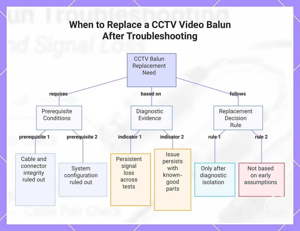
CCTV video balun replacement becomes necessary after troubleshooting only when signal failure continues under verified test conditions where cable integrity, connector stability, and system configuration have already been ruled out as primary causes.
Persistent signal loss across multiple validation attempts may indicate that the CCTV video balun is no longer maintaining stable transmission behavior. This is more relevant when the same issue appears even after controlled comparison with known-good components and consistent wiring conditions.
Replacement decisions remain conditional and should follow confirmed diagnostic isolation rather than early assumptions. Only when repeated evidence consistently points to internal balun failure or irreversible performance degradation does replacement become a justified next step in the system restoration process.
This chart shows the conditions and evidence that justify CCTV video balun replacement, based on diagnostic testing and exclusion of other causes.
Preventing CCTV Video Balun Signal Loss Through Proper Installation Practices
Preventing CCTV video balun signal loss starts with correct installation practices that ensure stable transmission through proper planning of termination quality, cable selection, and conductor pairing consistency.
Installation quality for CCTV video balun systems depends on maintaining correct termination standards, using suitable twisted pair cable types, and ensuring consistent pairing alignment across both ends of the transmission path. These factors collectively help reduce instability that may develop during long-term operation, especially when environmental or electrical conditions vary.
Proper implementation also connects to broader system design considerations found in the CCTV video baluns hub, where installation choices influence overall signal stability and reduce the likelihood of avoidable transmission loss. When these practices are applied consistently, the system is more likely to maintain balanced signal behavior across the entire cable run.
In many installations, adherence to structured wiring and termination practices may improve resistance to interference and reduce the chance of signal degradation over time, particularly in setups where cable length and environmental exposure vary. :contentReference[oaicite:0]{index=0}