CCTV Video Baluns Working Principle Over UTP Cable
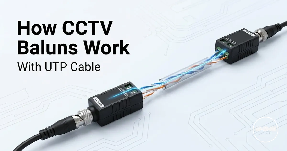
A CCTV video balun is a transmission component that enables analog video transmission over UTP cable by converting signals between unbalanced camera output and balanced twisted pair formats while supporting impedance alignment for stable communication between camera and DVR systems.
A CCTV video balun works through signal conversion that transforms the camera’s BNC-based unbalanced video signal into a balanced format suitable for transmission over UTP cable. This process helps reduce signal reflection through impedance alignment and supports resistance to interference across the cable infrastructure. At the receiving end, the balun converts the balanced signal back into an unbalanced format for DVR decoding, enabling continuous video transmission across the system.
In a typical setup, the camera outputs video through a coaxial BNC connection into the CCTV video balun, where signal conversion prepares it for travel across twisted pair UTP cable. The signal then moves through the cable infrastructure as a balanced transmission designed to support distance stability and interference resistance. At the DVR side, a second balun reconverts the signal for video processing, maintaining continuity from camera to recording system.
This end-to-end working principle maintains a continuous bridge between camera capture and DVR recording through structured signal conversion and controlled transmission across the network.
Conversion Between Balanced and Unbalanced Video Signals in CCTV Baluns
A balanced signal uses two conductors with opposite polarity, while an unbalanced signal carries the video signal over a single conductor with a shared ground in BNC-based CCTV systems. This concept is closely related to CCTV video balun meaning in practical transmission design.
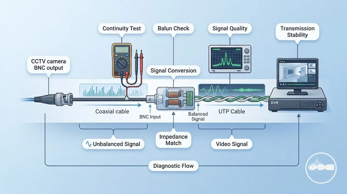
The conversion in a CCTV video balun transforms the unbalanced BNC video signal into a balanced format suitable for transmission over UTP cable. This signal adaptation supports impedance matching, which helps reduce reflection and maintain transmission stability across twisted pair wiring. By aligning signal behavior with the electrical characteristics of the cable infrastructure, the system improves video signal continuity and resistance to interference during transmission.
Direct transmission from a BNC unbalanced output over longer distances is limited because the video signal is more exposed to degradation and interference without balanced structure support. Without conversion, impedance mismatches and noise sensitivity can reduce signal integrity across standard UTP cable runs. This is why CCTV systems rely on balanced conversion through a CCTV video balun to maintain more stable video transmission between camera and DVR.
This conversion process ensures that signal behavior remains more consistent across different cable conditions, supporting overall transmission stability in CCTV installations.
How Video Travels Through Twisted Pair (UTP/CAT5/CAT6) Cable
After signal conversion in a CCTV video balun, the video signal propagates through twisted pair cabling as a balanced transmission designed to maintain signal stability over distance. This signal propagation distributes electrical energy across paired conductors, which helps reduce noise sensitivity compared to unbalanced transmission. The behavior of the signal inside the UTP cable depends on cable quality, environmental conditions, and proper impedance alignment.
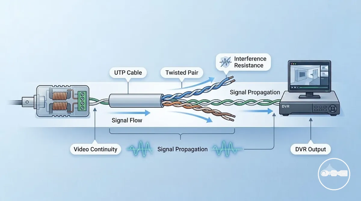
Inside CAT5, CAT5e, and CAT6 UTP cable, the video signal moves through tightly twisted copper pairs that improve interference resistance by cancelling external noise during signal propagation. The twisting structure of the cable supports more stable transmission behavior, although attenuation and signal loss may still vary depending on distance and installation environment. In many CCTV setups, CAT5 and CAT6 cables are used as the transmission medium after the CCTV video balun converts the signal into a balanced format suitable for twisted pair infrastructure.
For example, a CCTV camera sends video through a BNC connection into a CCTV video balun, where it is converted into a balanced signal before entering the UTP cable. The signal then travels through the twisted pair structure toward the DVR, where it is received and processed back into a viewable video feed. This camera-to-DVR flow depends on stable signal propagation through the cable path, supported by interference resistance and consistent transmission behavior across the network.
This transmission path helps maintain video continuity from camera to recording system by maintaining controlled signal behavior through twisted pair infrastructure.
Electrical Attributes That Enable Stable CCTV Video Transmission
Stable CCTV video transmission through a CCTV video balun depends on electrical attributes such as impedance matching, noise rejection, and bandwidth behavior. These attributes define how signal quality is maintained while the video travels through UTP cable, especially under varying installation and environmental conditions. Their combined effect helps control degradation and supports more consistent signal stability over distance.
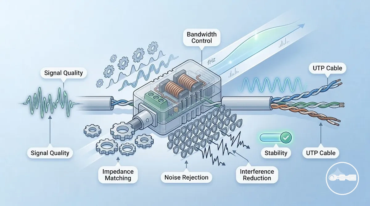
Impedance matching controls how efficiently the signal moves between the CCTV video balun and UTP cable, reducing reflections that can reduce clarity. Noise rejection reduces the influence of electromagnetic interference, helping preserve cleaner transmission where external electrical activity is present. Bandwidth behavior determines how much signal information can pass through the system, influencing overall signal quality and consistency during propagation.
When these attributes operate together, they support more stable transmission by reducing signal loss and maintaining consistency in video delivery. Depending on cable quality and environmental interference, the balance between impedance, noise rejection, and bandwidth can directly affect how clearly the CCTV video balun preserves video continuity to the receiving system.
Impedance Matching and Noise Rejection in Video Balun Performance
Impedance matching in a CCTV video balun is the alignment between source and cable impedance that reduces signal reflection and distortion. This alignment minimizes mismatch effects that can otherwise weaken signal stability during transmission.
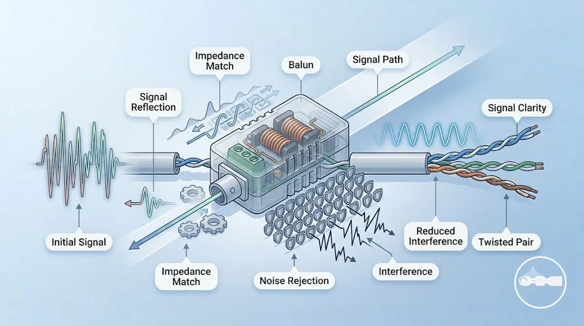
Noise rejection describes how the balun and twisted pair structure reduce electromagnetic interference affecting the video signal. By limiting interference pickup, it supports cleaner transmission behavior and reduces noise-related signal disruption.
- Impedance matching reduces signal reflection and distortion from mismatch
- Noise rejection limits electromagnetic interference impact
- Twisted pair structure improves shielding behavior against external noise
- Combined effect improves signal clarity and transmission stability
Together, impedance matching and noise rejection reinforce each other to maintain clearer and more stable CCTV video balun performance under varying interference and cable conditions.
Bandwidth Behavior and Distance Effects in UTP Video Transmission
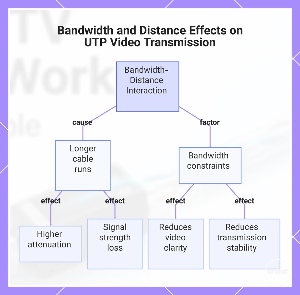
Bandwidth behavior in UTP video transmission describes how bandwidth capacity interacts with transmission distance to influence signal quality and stability. In a CCTV video context, increasing distance places greater demand on bandwidth consistency, which can affect how reliably video data is carried through the UTP cable.
As distance increases, attenuation becomes more pronounced, leading to gradual signal loss across the transmission path. This reduction in signal strength can result in lower video quality, often appearing as reduced clarity, increased instability, or inconsistent signal performance depending on cable conditions.
- Distance increase raises attenuation levels in UTP cable
- Signal loss reduces effective transmission strength over length
- Bandwidth limits reduce clarity and stable video delivery
Overall, longer UTP cable runs require careful consideration of bandwidth and distance trade-offs, as exceeding optimal transmission conditions can gradually reduce video quality and system stability.
This chart shows how increasing distance and bandwidth limitations interact to degrade video signal quality and stability in UTP cable runs.
Transmitter–Receiver Roles in CCTV Video Balun Pairs
A CCTV balun pair is a transmitter-receiver system that enables signal conversion and transport between a camera and a DVR. It defines a role-based structure where video signals are processed through signal conversion and transferred across the system for display and recording.
The transmitter role operates on the camera side, where the incoming video signal is converted into a transmission-ready format. The receiver role operates on the DVR side, where the incoming signal is reconverted into a usable video output. This role separation supports clear function mapping between input and output stages within the CCTV balun pair system and helps maintain signal integrity under compatible conditions. Performance consistency may vary depending on cable quality and system compatibility factors.
| Transmitter (Camera Side) | Receiver (DVR Side) |
|---|---|
| Converts camera video into transmission-ready signal | Reconstructs received signal into display video |
| Handles outbound signal preparation | Handles inbound signal recovery |
| Initiates signal conversion process | Completes signal reconversion process |
Together, the transmitter and receiver roles form a coordinated CCTV balun pair system that supports stable signal behavior when system compatibility and transmission conditions are properly aligned.
End-to-End Signal Flow from CCTV Camera to DVR via Balun System
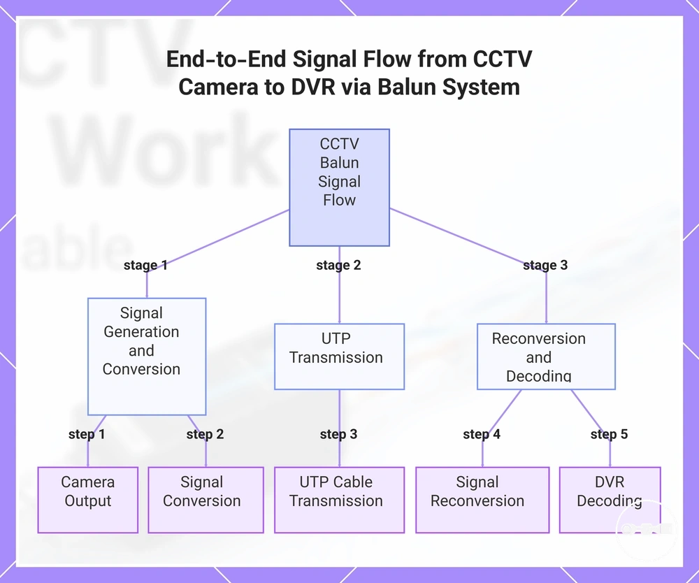
The signal flow in a CCTV video balun system is a complete transmission path that connects a camera to a DVR through the balun system using signal conversion, UTP cable transmission, and reconversion stages. This end-to-end signal flow describes a continuous pipeline where video data moves step by step from input to final decoding under variable transmission conditions.
The full signal flow follows a linear sequence of stages within the balun system:
- Camera Output – the camera generates the original video signal
- Signal Conversion – the balun system converts the signal for transmission
- UTP Transmission – the signal travels through the UTP cable as part of the transmission path
- Signal Reconversion – the receiver restores the original signal format
- DVR Decoding – the DVR processes the signal for display and recording
This signal flow depends on the integrity of the transmission path, where distance, interference, and cable quality may influence overall signal stability and reconstruction quality within the CCTV balun system.
This chart shows the linear sequence of stages in the CCTV balun signal flow, from camera output to DVR decoding.